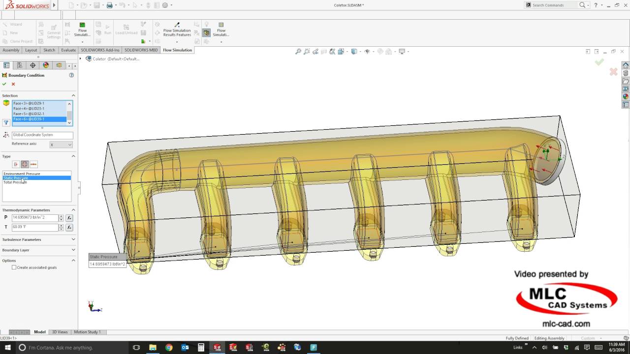
solidworks flow simulation boundary conditions
SOLIDWORKS is a premier CAD solution for 3D design and product data management. Hydrologic Engineering CWR 4202 3 credits Prerequisite.

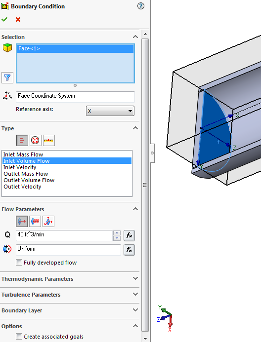
Applying Boundary Conditions In A Flow Study In Solidworks Youtube
This saved us and the customer up to four weeks in external review and 5 to 10K in assessment costs and kept the.
. CWR 3201C with minimum grade of C. The physics-controlled mesh functionality in the CFD Module takes the boundary conditions in the fluid flow problem into consideration when generating the mesh sequence. The Data Surface Editor sets up and edits complex spatial load.
Provides a streamlined process of definingmodelling and placing bolts in a model. Understand the impact of changes in the geometry or boundary conditions on the results effortlessly conduct fast. When used together with multiphysics simulation it provides a powerful.
And parts drawn on Solidworks. Manages step dependent objects like loads boundary conditions interactions predefined fields field output requests in a manager-style dialog box. The LiveLink for SOLIDWORKS add-on to COMSOL Multiphysics delivers connectivity tools between the two programs so you can efficiently integrate simulation into your design workflow.
Simcenter FLOEFD software puts the power of CFD simulation in your hands. Talking of animation is 3DS Max is possible and equivalently same. -Turbulence models and Boundary conditions -Solving flow in pipe comparing different cases CFX.
I got used to EMS very fast. By leveraging our unique inherently transient Lattice Boltzmann-based physics PowerFLOW CFD solution performs simulations that accurately predict real world conditions. FEMAP Prepost-processor for FEA modeling and simulation.
Once complete the results can be analyzed either from within Fluent via CFD-Post or via Ensight. When editing the boundary feature you can drag 3D sketch segments points or planes from the 3D sketch from which contours have been defined for the boundary feature. The blue surface would have been difficult to create any other way but the Fill surface handles this with ease.
Once all of the boundary conditions physics settings and solver settings are ready the simulation can either be launched directly from within Fluent or via a batch or job submit script this does require the case and data files to be written. My graduation project was about the CFD simulation a morphing wing using ANSYS-Fluent I used advanced tools like Dynamic mesh and. Fundamental properties of incompressible fluids.
A boundary layer mesh is automatically generated in order to resolve the gradients in velocity that usually arise at the surfaces where wall conditions are applied. Plugin 3-Abaqus Bolt Studio. A user will find the animation work much customizable in Maya if he knows a bit of language like Python or MEL scripting language.
Use it directly in NX Creo CATIA V5 or Solid Edge in order to explore the full potential of your ideas quickly without disrupting your design process. Monitor execution of the simulation in the solver window. One of the simplest things a Fill surface does is to simply fill a hole in a model.
Plugin 2-Abaqus Auto Mesher. Simufact Forming takes into account all areas of forming technology and therefore ensures a highly realistic simulation of the processes. Have a clear understanding of the problem.
SOLIDWORKS Flow Simulation is a CFD software designed for the everyday SOLIDWORKS user and analyst. And also the options to plot the results are very nice and intuitive. Now I work as teaching assistant at the same department.
Think the complete workflow through Having an idea about the mesh and the application of boundary conditions can help with CAD preparation. In the end the results of the simulation matched very well with the experimental values. Trims surfaces by direction when curves do not form a closed boundary.
I just needed two days to get a first result. When we look at the available results of a model that has negative eigenvalues we want to look for areas that might be buckling or overly strained and re-evaluate how the. And boundary conditions to the model.
In external studies the computational domain acts as our virtual wind tunnel with boundary conditions heat sources and transient behavior all applied. We were able to run a thermal and fluid flow analysis with SOLIDWORKS Flow Simulation within 24 hours to confirm that the product supplied would work and that the anti-icing would have no hot or cold spots on the separator vanes. Preliminary design of hydraulic structures.
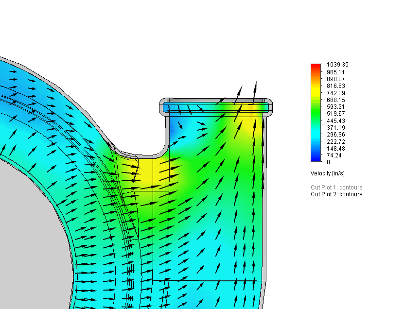
Postprocess results using cut plots surface plots flow trajectories. Launch the SOLIDWORKS Flow simulation and monitor it in the solver window. Using the PowerFLOW suite engineers evaluate product performance early in the design process prior to any prototype being built when the impact of change is most significant for design and.
Solve the problem using the displacement control method. A proven strategy for the simulation setup is to create it for a very simple version of the problem in order to see whether or not the simulation approach is viable. Nastran Unlocked Extension.
We achieve this high degree of precision by using boundary conditions and representations that have been conceived with the demands of the user in mind. It provides dynamic feedback on the fluid flow and thermal performance of their products. The hole might exist because it is the last gap in the modeling process or it might be a hole that was created intentionally to get rid of a blemish in.
Import geometry from any major CAD system Solid Edge Solidworks Autodesk CATIA Creo Pro-E NX and many more. Hydrostatics and fluid motion in closed conduits and open channels. Adjust boundary conditions for the displacement control method.
Trim by Profile. The recommendations for correcting negative eigenvalues are to re-evaluate your material models and ensure your boundary conditions and loading conditions are realistic. Especially the simplicity to apply boundary conditions or to refine the mesh at certain surfaces or solids is great.
The thing that creates a difference between Maya and 3Ds Max is the process flow ease of use and amount of tools available.
Flow Simulation Basic Concepts Engineers Rule
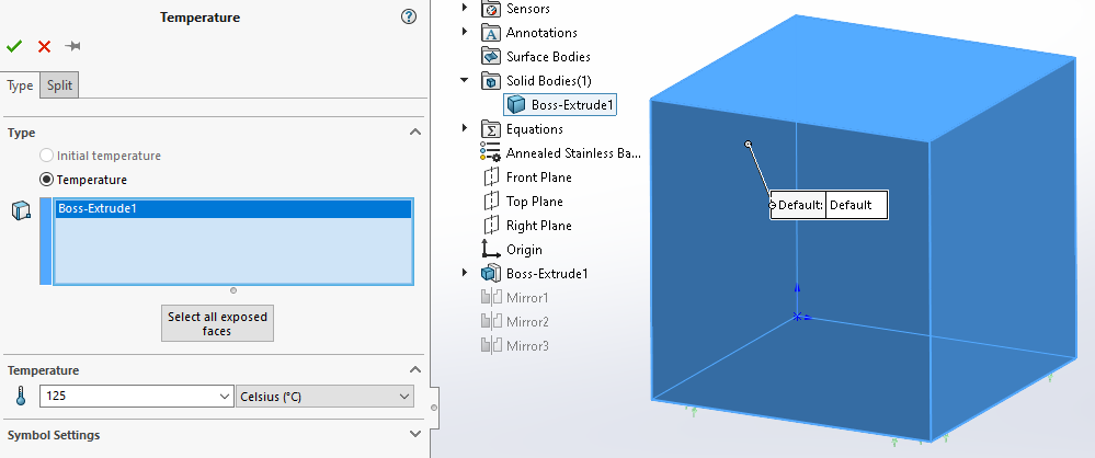
Solidworks Simulation Boundary Conditions And Linear Thermal Expansion Part 1 Solidworks Simulation Boundary Conditions And Linear Thermal Expansion Part 1
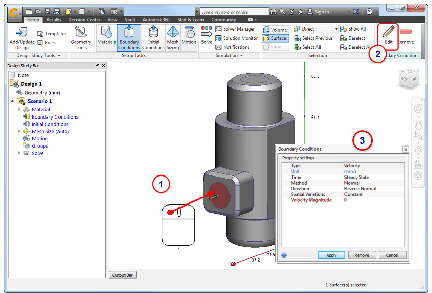
Boundary Conditions Cfd 2019 Autodesk Knowledge Network

Effect Of Boundary Condition In Thermal Analysis Using Ansys Analysis Thermal Finite Element
Solidworks Flow Simulation Boundaries And Goals Youtube

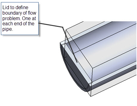
Tutorial Applying Boundary Condition In Flow Simulation Grabcad Tutorials

New Solidworks Simulation 2016 Enhancements To Make Your Analysis Easier Solidworks Mechanical Engineering Design Abaqus

Faster Results With Boundary Conditions Trimech

Symmetry Boundary Conditions In Solidworks Flow Sim

Slame Studio Solidworks Tutorial Berbahasa Indonesia Flow Simulation Solidworks Tutorial Solidworks Simulation

Throttle Flow Simulation Computer Aided Engineering Computer Simulation Simulation

Wave Generation Simulation Flow 3d Cfd Software Cfd Simulation Types Of Waves Simulation

Simulation Of The Air Flow Around A Football Computational Fluid Dynamics Fluid Dynamics Simulation

Draw An Aerofoil Using Imported Coordinate Data Points In Solidworks Tutorial Hd

Tutorial Applying Boundary Condition In Flow Simulation Grabcad Tutorials
Flow Simulation Basic Concepts Engineers Rule
Solidworks Flow Simulation Pressure Opening Explained

Flow Simulation Basic Concepts Engineers Rule

Faster Results With Boundary Conditions Trimech